|
|
|||||||||
|
|
|
||||||||
|
An
FSAT acts on propagating GWs as a spatial filter, which selects different
wavelengths (and hence frequencies) depending on the direction. This is
achieved through the particular geometry of the device, according to the
frequency-steerable directivity concept. |
|||||||||
|
Frequency-steerable
directivity Starting from the general
expression of elasto-dynamic equations which govern harmonic wave propagation
in a thin, plate-like structure: |
|||||||||
|
|||||||||
|
a
solution in the frequency-wavenumber domain is found upon Fourier
transformation of the space variables |
|||||||||
|
|||||||||
|
The
displacement amplitude can therefore be maximized by simultaneously
satisfying the following two conditions: |
|||||||||
|
|||||||||
|
i.e. each intersection between excitation
maxima and dispersion curves (circles for isotropic media) identifies a
wavenumber vector whose direction defines the direction of waves generated in
the plate. Different maxima can be selected by varying the excitation
frequency and hence the radius of dispersion circles, thus providing
frequency-based beam steering. Conversely, in sensing mode operation the
output signal spectrum exhibits peaks at different frequencies depending on
the incoming wave direction. |
|||||||||
|
Wavenumber spiral FSAT Beam steering at any
direction within an angular range up to [0, 180°] through a sweep of the
excitation frequency can be achieved by the three-step design approach
described below. |
|||||||||
|
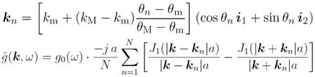
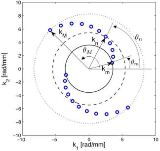
1. Wavenumber domain design The transducer design flow starts from defining the desired directivity
performance in the wavenumber plane. To achieve the target beam steering
behavior, maxima of the load distribution are arranged into a
spiral configuration in this domain, as shown in Fig. 1:
The spiral
shape allows for iso-frequency circles corresponding to a given wavenumber to
intersect a single directivity maximum, and therefore to identify a single direction
for the given wave vector: each angle is therefore related to a specific
frequency. |
|
||||||||
|
2. FSAT geometry derivation The device
geometry which provides the desired directional properties can be found from
the target frequency-wavenumber load distribution by inverse Fourier
transform (IFT), which yields the following expression:
This procedure is illustrated in Fig. 5(a)
and (b). The space-related component h(x) defines a circular patch of
radius a on which the harmonic load
amplitude presents a continuously varying modulation over the transducer
surface, according to sine-like terms. |
|||||||||
|
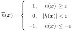
3. Thresholding The FSAT geometry calculated
at the previous step is practically unfeasible due to the continuous
amplitude modulation. However, a simpler and feasible configuration can be
achieved through a three-level quantization of h(x) based on a given threshold:
Fig. 2 (c) shows the
resulting two-channel transducer shape, while the corresponding wavenumber
performance is depicted on Fig. 2 (d), which does not exhibit significant
degradation compared to the target directivity design in Fig. 2 (a). |
|||||||||
|
|||||||||
|
|||||||||